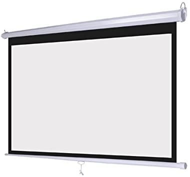
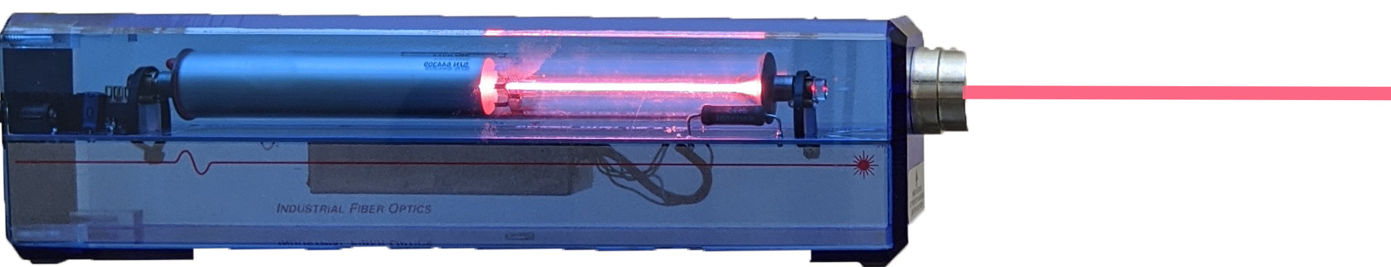
Laser light of wavelength 632.8 nanometers is aimed at a screen several meters away. A slit plate is placed near the laser, which blocks the laser light except when the beam is aimed directly through one of several tiny slit openings located within the plate. Slide the slit plate back and forth in front of the laser beam. When the beam passes through one of the openings in the slit plate, the light will diffract through the opening and create an interference pattern (i.e. diffraction pattern) on the screen located a distance of 5 meters away from the slit plate.
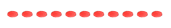
Choose the type of slit plate you want to use for your experiment. For the single slit plate the slit widths "a" are shown on the slit plate below each opening. For the double slit plate, the slit separations "d" are shown below each opening on the plate and the width of all individual slits "a" is also noted. For the multi-slit plate, the number of lines per centimeter is indicated below each opening and their resulting separation distance between neighboring slits "d" is also noted. The slit widths for the individual slits in the multi-slit plate are the same as widths of the slits in the double slit plate.
Note how the interference patterns on the screen change based on the type and dimensions of the different openings the laser light shines through. You can measure the distance between the middle of the bright central maximum and the middle of any of the dark or light regions to either side of it to verify that the appropriate constructive interference or destructive interference pattern holds true for the type of opening selected and its dimensions.
This simulation is based on real physical experiments in which some small amount of error between your measurements and the theoretically calculated results are to be expected. In addition, in the double slit and multi-slit plates, the combination of the diffraction pattern resulting from the particular width "a" of the individual single slits that make up a particular opening, overlaid on top of the double slit or mult-slit diffraction pattern of slit separation "d" associated with that opening, may cause some expected bright (constructive interference) regions to be "missing" - due to the fact that they are located where their single slit pattern produces desctructive interference, so there is no visible light intensity present at that position to interfere constructively as expected, thus producing a dark region where a bright region might have been theoretically anticipated based on the double-slit or multi-slit interference pattern alone.
When you have a diffraction pattern clearly visible on the screen, take a screenshot of the entire projection screen with the pattern on it so you can measure the distance to different bright and dark regions using a pixel measuring app. You may want to zoom in the web page so the
1. WINDOWS: use Windows-Shift-S to open a screen capture option where you can draw a box around the projection screen to capture and copy it to the computer's clipboard. MAC: use Command-Shift-4 to draw a box around the projection screen to put a screenshot file on your Desktop. Then double click that file to open it and select "copy" from the Edit menu to put it in the computer's clipboard.
2. Go to rapidtables.com/web/tools/pixel-ruler.html and use Ctrl-V or Cmd-V to paste your screenshot onto the page.
3. The white portion of the projection screen in this simulation is 14cm wide. Measure the screen width in pixels by drawing a line through the middle of the interference pattern horizontally from left to right and then read the pixels displayed in the box for this distance. You can now use this as a scaling factor (# of px per cm) to determine the actual distance between any two points on the image. For example, if you measure 140px for your 14cm screen width, and you then measure the distance between the middle of the bright central maximum to the middle of the first bright spot to one side and find it to be 5px, then you know that distance is actually 0.5cm or .005 meters [ 14cm/120px = ?cm/5px --> ? = 0.5cm ]
It is recommended that you measure the full distance between the same point of interest to either side of the bright central maximum and divide that value by 2 to get a more accurate result (the average of 2 measurement data points both measured to the same order number of bright or dark region, but on opposite sides of the center)
| Double Slit Slide | |||
|---|---|---|---|
| d=0.25mm | d=0.50mm | d=0.75mm | d=1.00mm |
| a=0.15mm for all slits | Multi Slit Slide | ||
| d=0.50mm | d=0.25mm | d=0.125mm | |
| a=0.15mm for all slits | Single Slit Slide | ||
| a=0.075mm | a=0.15mm | a=0.4mm | |