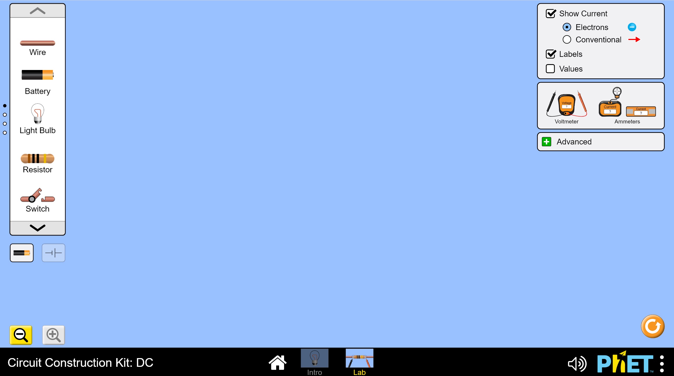
On the intro screen, double-click the option to open the "Lab" version. You will be take to a screen that looks like the following:
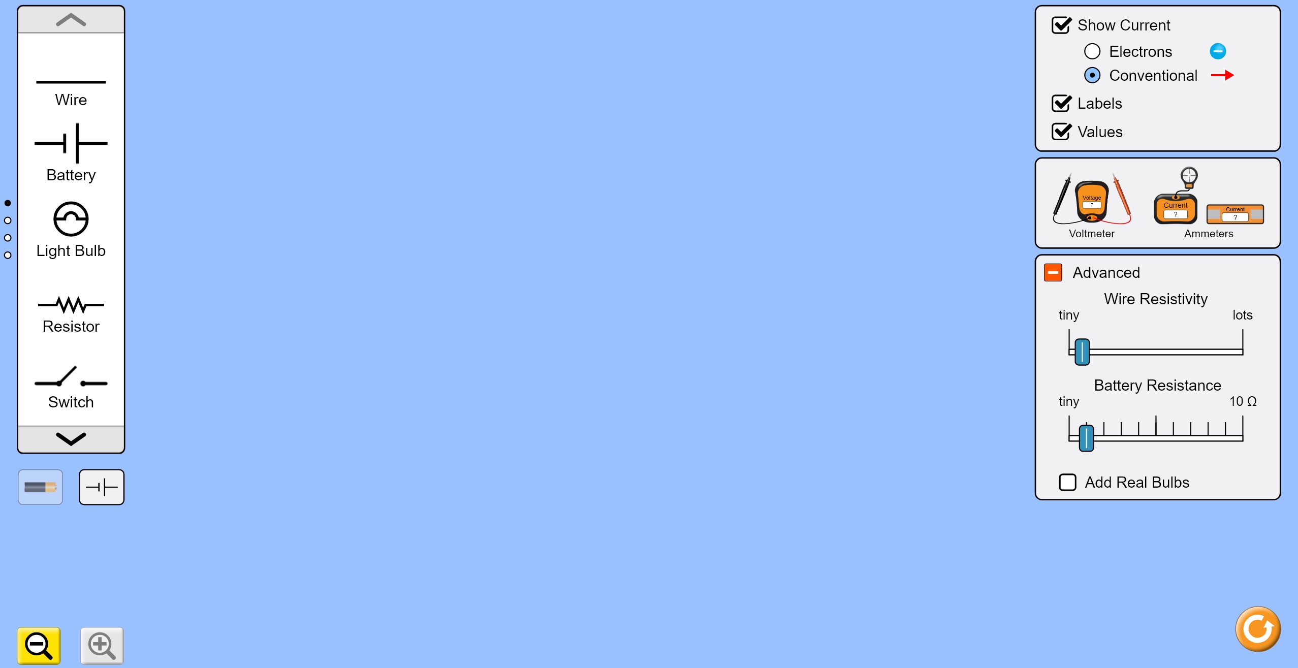
Make the following changes on the right hand side of the screen:
The screen should now look like something like this:
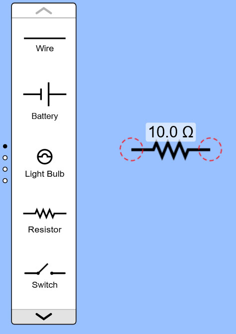
You can drag items from the tool palette on the left side of the screen. Drag over a Resistor onto the main screen and you will notice it defaults to 10 ohms as shown below.
If you use the down arrow at the bottom of the tool palette, it will move to the next set of available tools. Notice the black dot has moved to the second circle on the far left. This tells you that you are looking at the second of four sets of available tools.
You can see that some of the tools available in this second set are identical to what was in the first set. But, if you drag over a Resistor from this set of tools you will see that it defaults to 1000 ohms as shown below:
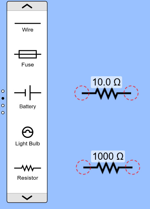
The second set of tools provide higher value options, which are what you will need for this lab.
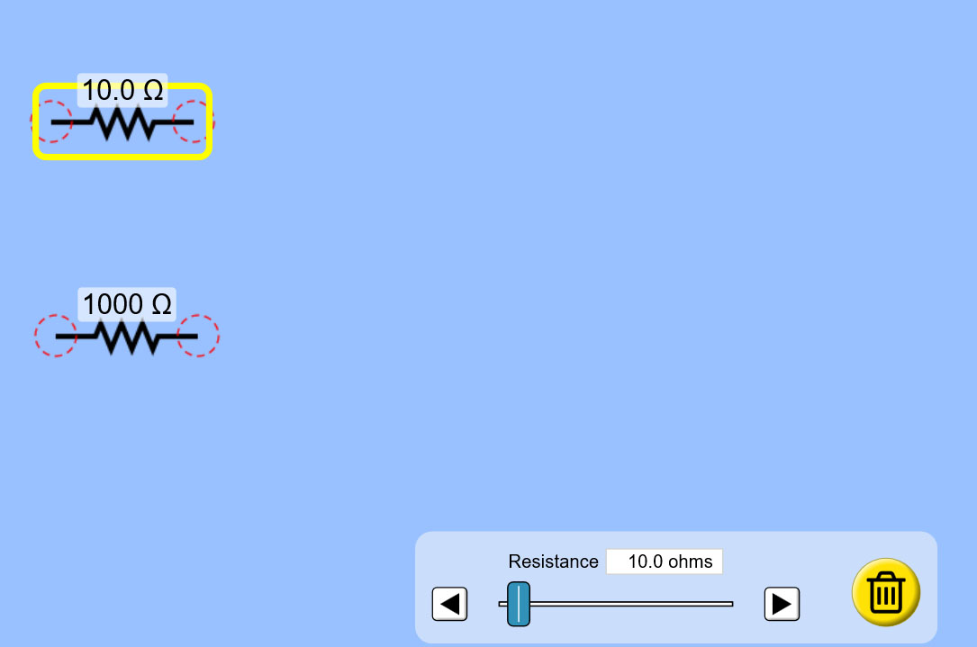
Let's get rid of the first 10 ohm Resistor you inserted. If you click on it, a yellow box will appear around it and an option box will appear at the bottom of the screen, as shown below. If you click on the trash can icon in the options it will remove the selected Resistor.
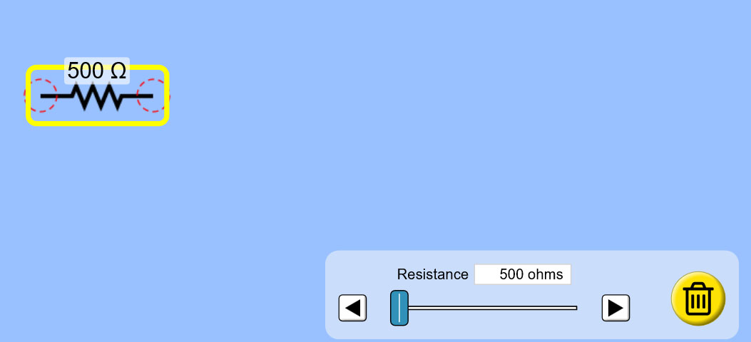
Now you can click on the 1000 Ohm resistor and in the option box that appears change the value using the slider bar until it reads 500 Ohms as shown here:
Drag your 500 Ohm resistor over to the side more and then drag 2 different Batteries (Voltage supplies) from the tool bar - 1 from the first set of tools and 1 from the second set of tools.
Again you will see that the tools differ in their values as shown here: (the resistance value for the small amount of "battery resistance" you added at the start may also be displayed next to it)
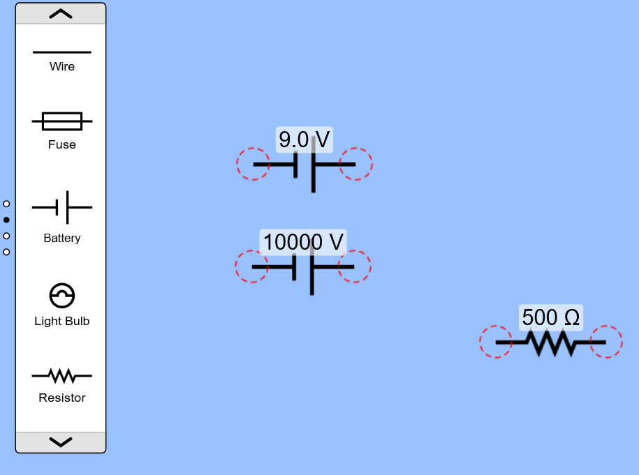
Delete the 10000 Volt battery so that you only have the 9 V battery and your 500 Ohm Resistor remaining on the screen.
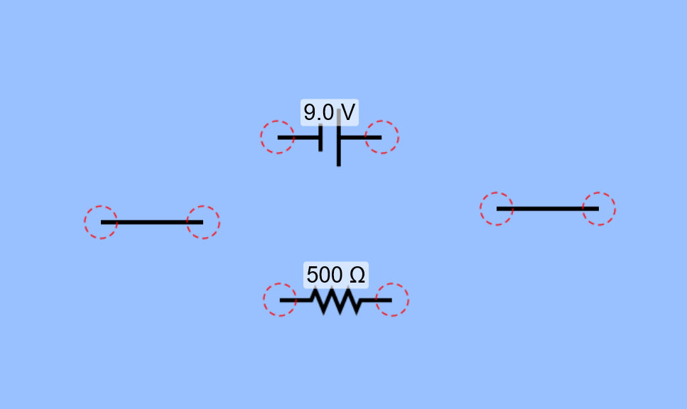
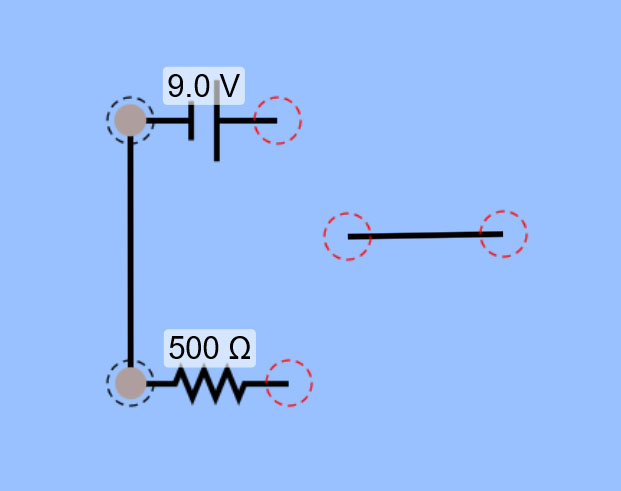
Now drag over a couple of wires onto the screen as shown:
You can drag the wires around the screen by selecting the middle of the wire. You can stretch and turn the wire by selecting either end of it. Try it out.
When your comfortable with handling the wires, use one wire to connect the ends on one side of the Voltage supply to the Resistor. You can verify they are connected by the fact that the circles that represent the junction between each connected element is now filled in with a solid brown circle instead of an empty red dashed circle like the disconnected elements have.
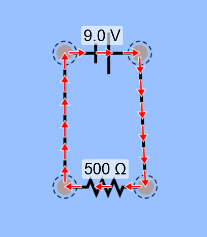
Now use the second wire to connect the other sides of the Voltage Supply and Resistor together.
Viola! You've made your first circuit. Notice that red arrows appear pointing in a circle around the elements of your circuit, representing the flow of current through the circuit from the positive Voltage terminal to the ground (0 Volts) terminal.
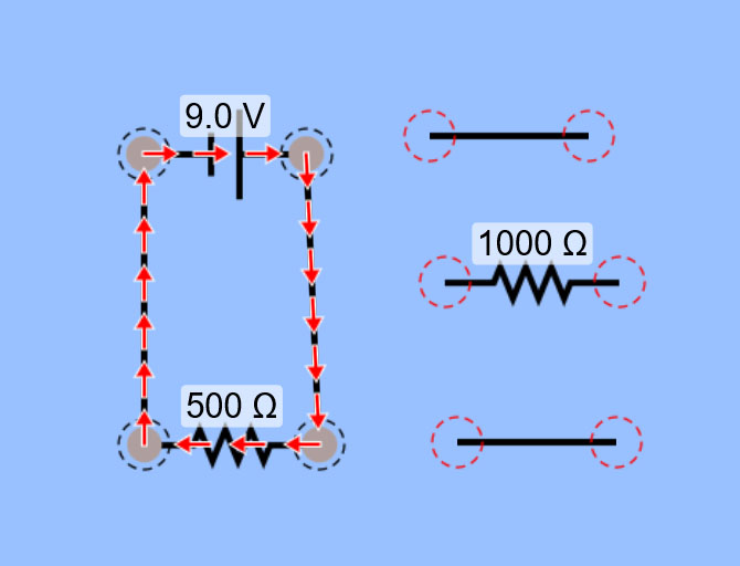
Let's add another Resistor. Grab another Resistor from the second set of tools and drop it onto the screen, along with 2 more wires.
Connect one side of the Resistor to your circuit with one of the wires and the other side with the other wire. You may find that the elements don't quite line up nicely when you try to do this.
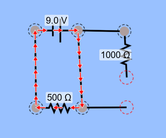
Don't worry, it's easy to fix things in a way that keeps it all neat and orderly looking by simply adding another wire into any unconnected spaces between elements as shown here:
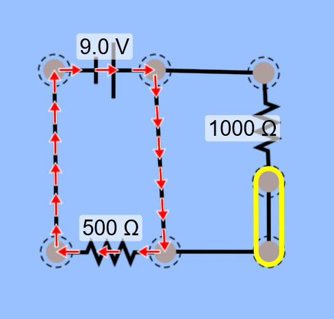
Why isn't there any current flowing through the new Resistor and wires you added?
If you look carefully, you'll notice that you have a wire that is "short circuiting" your circuit such that almost all the current coming out of the battery will go through this wire of nearly zero resistance and so almost none of it (or at least too little to measure) will go through the new Resistor you added as it has a much higher resistance to current flow.
To fix this you'll need to remove the short-circuiting wire. If you click on the junction at one end of this wire a yellow circle appears around it and a pair of scisscors appears. If you click the scisscors you are "cutting" this junction open. Try it.
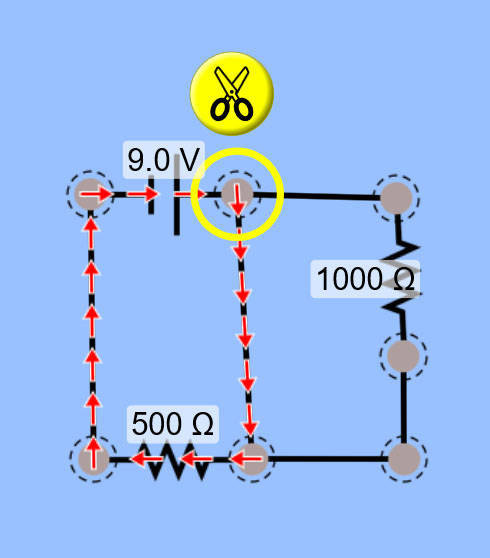
Now with the junction cut apart we no longer have any current flowing because we have opened the circult.
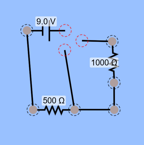
Select the unwanted wire and delete it using the trash can icon in the options.
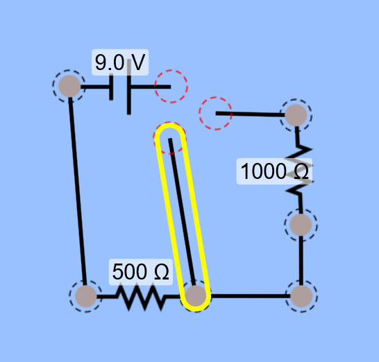
Now reconnect the remaining ends to complete your circuit again (close the circuit).
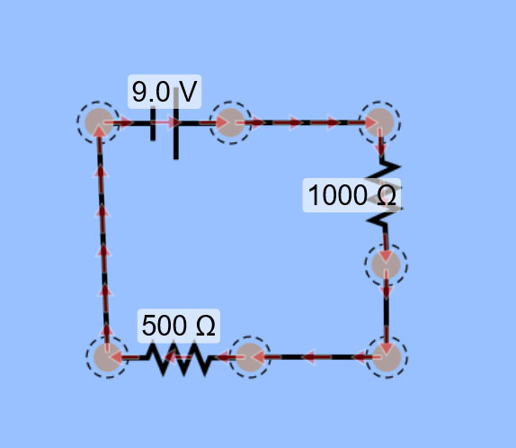
Now you have a circuit with a Voltage supply and 2 Resistors in SERIES. You can tell they are in series because the current that flows into one Resistor must continue on into the next Resistor without any other option for direction of flow.
Now let's try building a circuit with 2 Resistors in PARALLEL.
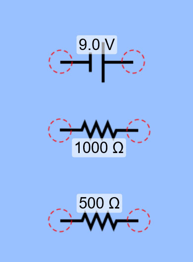
Remove all the wires from your previous circuit and lay out your Voltage supply and Resistors as shown:
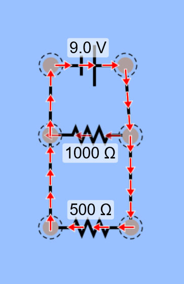
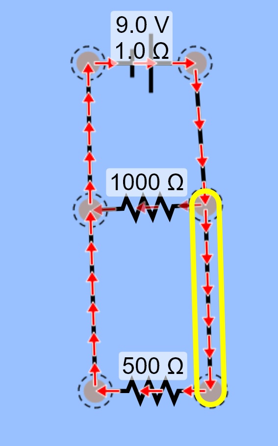
Use wires to connect them so that each side of both Resistors has a direct connection to the Voltage supply. This means that the potential difference across both Resistors should be the same as the Voltage supply potential. This puts the Resistors in parallel with each other and the current flow is as shown below, with more current going through the path with less resistance, represented by heavier shaded arrows over the 500 Ohm resistor as compared to the 1000 Ohm resistor.
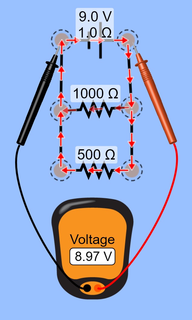
For your lab you're going to want to measure Voltage and Current at different points in your circuits you assemble. Drag over a volt meter from the tool palette on the RIGHT side.
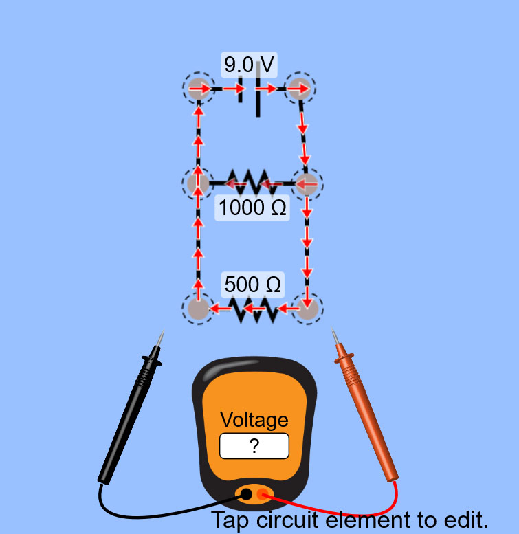
If you drag the test leads to various points in the circuit you can read out the Voltage across the span between the leads. For example, if you put a lead directly to either side of the Voltage supply, the readout on the meter tells you what the Voltage supply is providing. Ideally this should be the value you set for the battery, but since you included a small amount of "battery resistance" in the settings it will end up being slightly less than the ideal amount.
You can try moving the leads to different points and see if there is a change in the potential difference depending on where you test it. Since this is a parallel circuit, you should read the same potential difference across each of the elements in parallel with each other. However, since you included a small amount of "wire resistance" in the settings you may find that elements with greater lengths of open wire between the test probes have slightly lower potential due to the small amount of resistance the wire adds.

To measure the current you have 2 options in the tool palette on the right. For this tutorial we'll be using the inline ammeter element as this most closely matches how you would likely measure the current in a physical circuit.
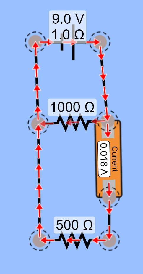
Let's try checking the current going through the branch of the circuit that flows through the 500 Ohm Resistor. First, remove the wire that's currently between them.
Now replace the wire with the ammeter element. You may need to add an extra wire to connect everything in a clean and organized looking manner.
When the circult is properly connected again you will see the current readout for the location of the ammeter as shown:
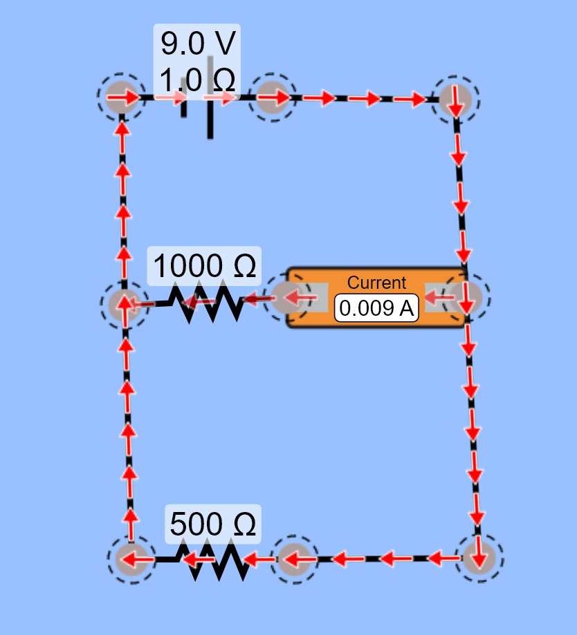
If you want to check the current specifically going into the 1000 Ohm Resistor, you will need to make sure the ammeter is placed in series with that Resistor. Rearrange your circuit to place the ammeter in series with the 1000 Ohm resistor. You will probably need to cut open some of the junctions and add extra wires to finish the circuit in a clean, organized fashion. As you can see, the ammeter in this circuit simulator is limited to 3 decimal places of precision. So your current measurements (and hence, current calculations) will be limited to this number of significant figures.
You have completed the tutorial and should now have the basic understanding of how to use the virtual dc circuit lab app. Follow the procedures in your lab procedures, building the necesary circuits as required for each step.
BE SURE TO WATCH THE LAB INTRO VIDEO FOR HELPFUL HINTS AND A RUN THROUGH OF WHAT THE PHYSICAL IN-PERSON VERSION OF THIS LAB LOOKS LIKE.