On the intro screen, double-click the option to open the "Lab" version.
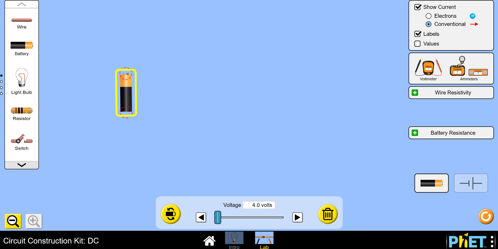
For this lab, instead of using the circuit diagram images, we will use the item pictures. This is represented by the picture of a battery in the lower right hand corner of the screen. Begin by placing a battery on the desktop and set its voltage to 4V to match what you would have used in the light bulb portion oof the hands-on version of this lab, as shown in the image below:
Now add wires and a light bulb to create a simple circuit. The connections for the light bulbs are located very close to each other, so watch carefully when you're connecting them to make sure that you have your wires properly aligned. You can click on the bulb to adjust its resistance. Use 2 Ohms for the resistance of this bulb, as was found for bulb R1 in the demonstration video for this lab, as shown below:
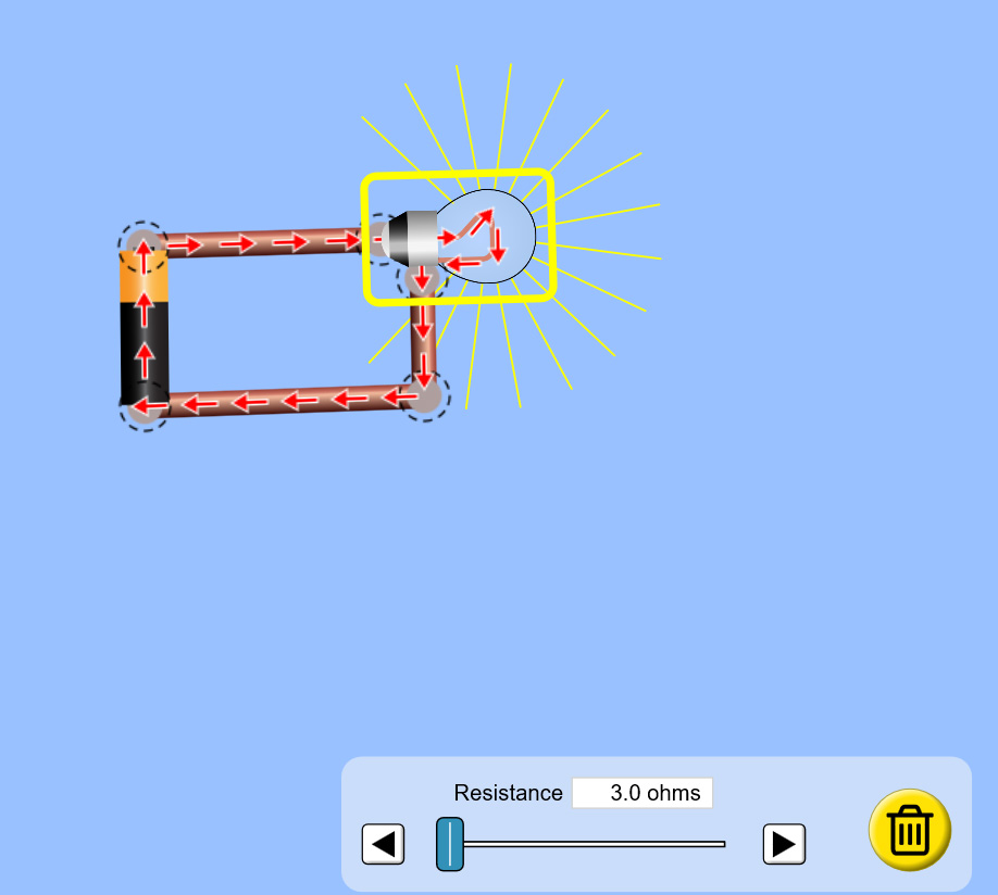
Notice how the brightness of the bulb is indicated by the yellow rays coming out of it. Try changing the resistance of the bulb and the voltage of the battery to see how it changes the brightness. You will use this feature to compare relative brightnesses of different bulbs in different configurations.
Due to the configuration of the connectors on the bulbs, you'll want to practice a little with how to set up series and parallel circuits using light bulbs.
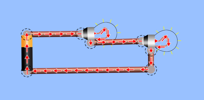
Here is a suggested way you can arrange 2 bulbs in series (below). Notice how I have made sure that the wire from one end of the battery comes in to one connector of the first bulb, then out of its second connector and into the first connector of the second bulb, and then out of the second connector of the second bulb back to the other end of the battery to complete a series circuit requiring the current from the battery to flow through first one bulb and then the other bulb in series. I have set the resistance of both of these bulbs to 2 Ohms and the batery voltage to 4 Volts.
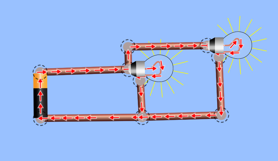
And here's a suggested way you can arrange 2 bulbs in parallel (below). Notice that I carefully arranged things so that the wire coming out of one end of the battery is directed to the same connector on both bulbs, and the other end of the battery is directed to the opposited connector on both bulbs, to ensure the same voltage potential is achieved across both bulbs. Again, both bulbs have a resistance of 2 Ohms and the battery has a voltage of 4 Volts in this example.
For your lab procedures, you will use 4V for the power supply (battery) voltage, and use the following values for resistance for each bulb:
R1 = 2 Ohms
R2 = 2 Ohms
R3 = 3 Ohms
R4 = 4 Ohms
Be sure to set each bulb value accordingly.
These are your "measured" resistances for each bulb. You will be using a 4V power supply and R1 through R4 for lab procedures Parts I, II, and III.
For lab procedures Parts IV and V you will repeat the procedures from Parts II and III, but you will increase the power supply voltage to 5V and replace light bulbs with 1000 Ohm resistors.
1000 Ohm resistors can be found in the second set of tools in the tool bar on the left side of the screen. Feel free to use either the circuit elements or pictures version of the virtual lab elements, whichever is easiest for you to work with visually.
Since you are defining the resistance of the resistors in the circuit as 1000 ohms, the "measured" value of all of the resistors will be 1000 ohms.